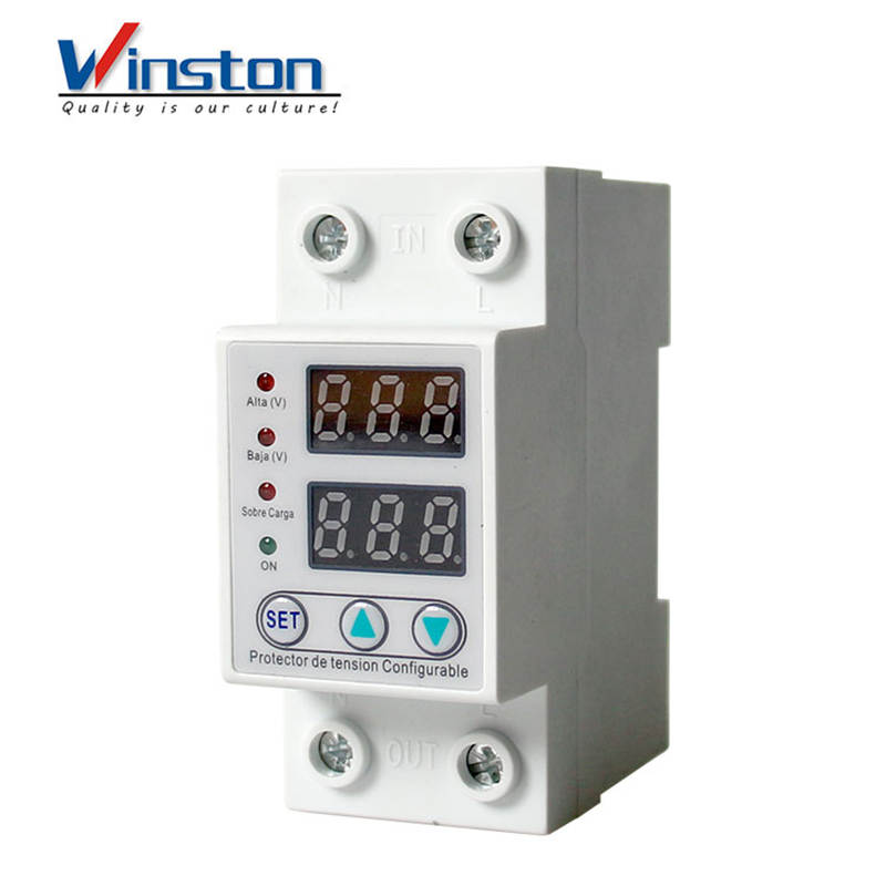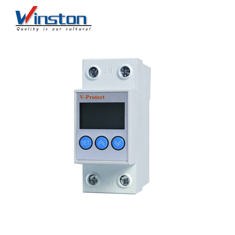
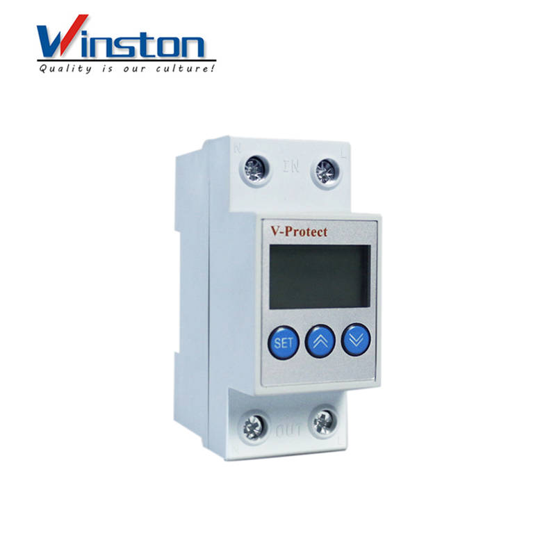
63a Smart Over under voltage Current Protector Regulators/Stabilizers
I. Purpose
Smart over-/under-voltage current protector is a comprehensive smart protector that integrates functions suchas overcurrent protection, over-voltage protection, under-voltage protection, voltage measurement, voltage display, current measurement and current display protection. In the event of overcurrent, overvoltage or under-voltagefaults, the protector can cut off the power supply instantaneously and protect the electrical equipment from beingburned out. When all lines return to normal state, the protector can automatically restore power. The overcurrent value, overvoltage value, overvoltage recovery value, under-voltage value, under-voltage recovery value, actuationtime, recovery time and power-on time of the product, functions like fault memory and inquiry and reset can be set as required. The real-time voltage value and current value are displayed cyclically. Each time you press the button"∨", the voltage or current to be displayed separately while you press the button"∧", all the alternatives canbe display. It is so flexible that it can be used as a voltmeter or ammeter. Users can choose the appropriate type ofprotector according to the actual situation.
II. Main technical parameters
|
Product model |
WD-F63 |
|
Rated voltage |
230V50Hz |
|
Rated current |
1A ~ 63A (adjustable), 63A (default) |
|
Under-voltage protection value range |
OFF-210V-150V (adjustable), 160V (default) |
|
Over-voltage protection value range |
221V-300V-OFF (adjustable), 280V (default) |
|
Recovery delay time |
2 ~ 512s (Default 60s) |
|
Delay time for power-on |
2 ~ 255s (Default 2s) |
|
Power consumption |
≤2W |
|
Electrical and mechanical lifespan |
≥40 thousand times |
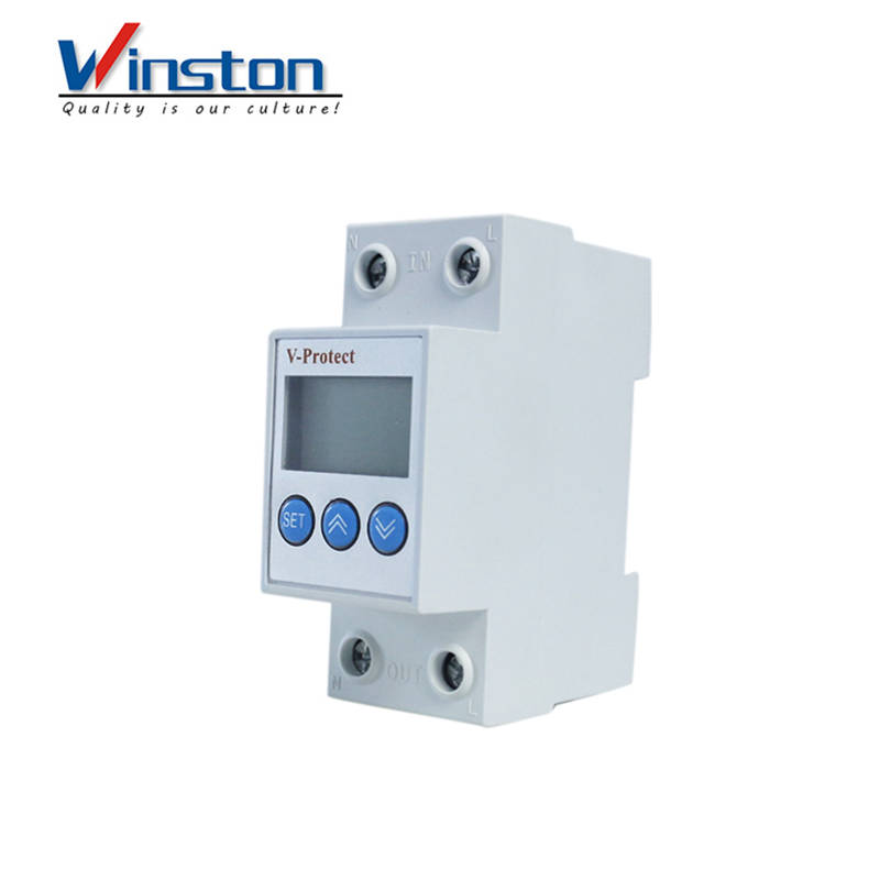
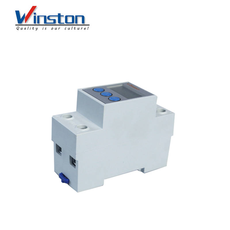
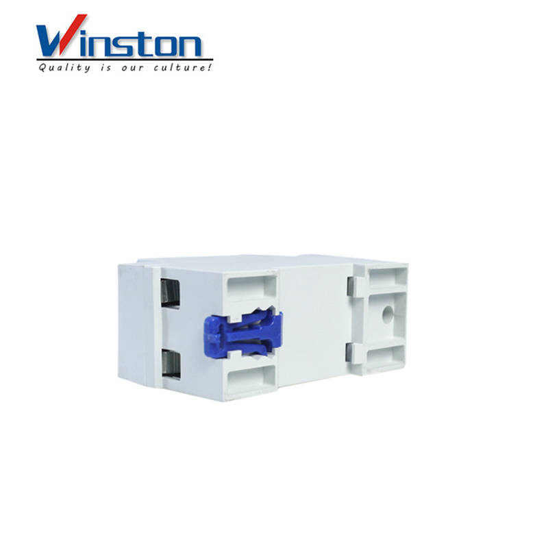
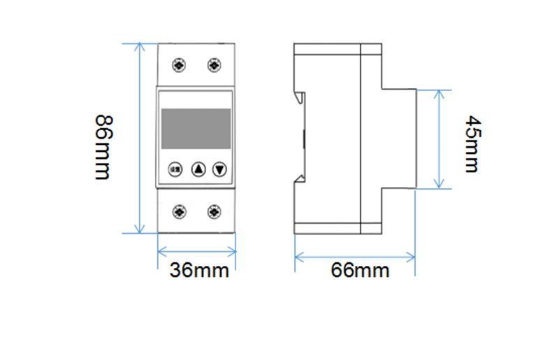
III.Product Dimensions
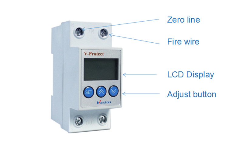
IV.Product introduction
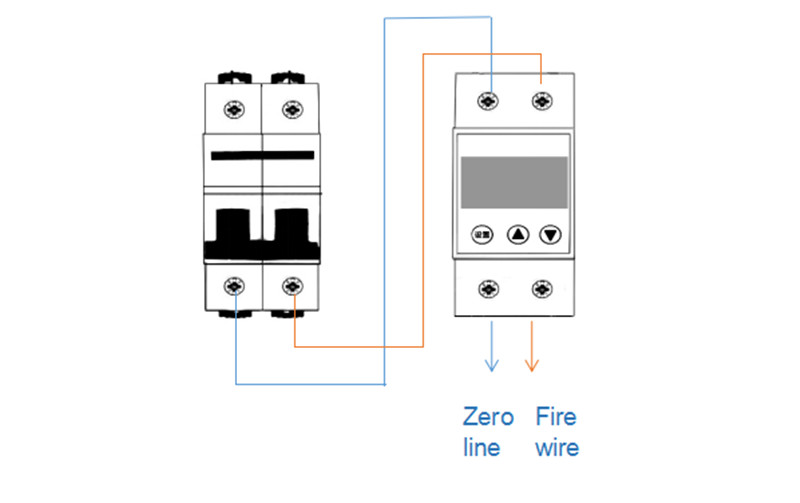
V.Product connection diagram
VI.Method of setting parameter
Under normal conditions, press and hold "setting" for 3 seconds to enter the "setting" state. The above Nixie tube displays "P 01" and the lower Nixie tube displays "280". P 01 means that the first parameter set is the overvoltage value, "280" means the default overvoltage value is 280V, press "∧" or "∨" to modify the overvoltage value. When the overvoltage value is adjusted to 300V, press the button "∧". The display shows OFF, indicating that the overvoltage protection function is off. The modification range is 221V - 300V - OFF; Press thbutton "setting" again to set the overvoltage recovery value. The upper Nixie tube displays "P 02" and the lower Nixie tube displays "250". P 02 indicates that the second parameter set is the overvoltage recovery value, and"250" indicates the default overvoltage. The recovery value is 250V. Press "∧" or "∨" key to modify the overvoltage recovery value. When the overvoltage protection setting is off, the overvoltage recovery value will beautomatically turned to OFF. The overvoltage recovery value is modified from 220V - 300V- OFF. Press the button"setting" again and set the overvoltage protection actuation time. The upper Nixie tube displays "P 03" and thelower Nixie tube displays "0.1". P 03 means that the third parameter set is the overvoltage actuation time, "0.1" means the default overvoltage action time is 0.1 second, press "∧" or "∨" key to modify the overvoltageactuation time value, the modification ranges from 0.1 to 10 seconds; The default value is 0.1 second, and it isrecommended to be ≤ 0.1 second.
Press the button "setting" again, the above Nixie tube displays "P 04", and the lower Nixie tube displays "160". P 04 indicates that the fourth parameter set is the under-voltage value, and "160" indicates that the default under-voltage action value is 160V. Press "∧" or "∨" to modify the under-voltage action value, and the modification range is OFF-150V-219V; Press the button "setting" again to set the under-voltage recovery value. The upper Nixie tube displays "P 05" and the lower Nixie tube displays "180". P 05 indicates that the fifthparameter is the under-voltage recovery value, and "180" indicates the default under-voltage. The recovery value is 180V. Press "∧" or "∨" key to modify the under-voltage recovery value. When the under-voltage protection valueis adjusted to 150V, press "∨" to display OFF, indicating that the under-voltage protection is off, and thunder-voltage recovery value is modified. OFF-151V-220V, press the button "setting" again to set the under-voltage protection actuation time, the above Nixie tube shows "P06", the lower Nixie tube shows "0.1". P 06 means that the sixth parameter set is the under-voltage actuation time, "0.1" means the default overvoltage actiontime is 0.1 second, press "∧" or "∨" key to modify the under-voltage actuation time value, the modificationranges from 0.1 to 30 seconds; The default value is 0.1 seconds, and it is recommended to be ≤ 0.5 seconds. Note: After the under-voltage actuation time is set longer than 0.5 seconds, the relay cannot be driven due tothe power fault of the MCU. Therefore, when the setting time is longer than 0.5 seconds, the grid cannot be disconnected when the power is cut off.
Press "setting" again to set the current limit parameter. The above Nixie tube displays "P 07" and the lower Nixie tube displays "63". P 07 means that the seventh parameter set is the overcurrent value, "63" means the default overcurrent protection value is 63A, press "∧" or "∨" key to modify the overcurrent protection value, modification range is 1A - 63A; Press the button "setting" again to set the overcurrent protection actuation time. The upper Nixie tube displays "P 08" and the lower Nixie tube displays "5.0". P 08 means that the eighthparameter set is the overcurrent actuation time, "5.0" means the default overvoltage action time is 5.0 second, press "∧" or "∨" key to modify the overcurrent actuation time value, the modification ranges from 0.1 to 512 seconds;the default value is 5.0 seconds. It depends on the service condition.
Press "setting" again to set the delay time for fault recovery. The above Nixie tube displays "P 09" and the lower Nixie tube displays "60". P 09 indicates that the ninth parameter set is the fault recovery time value, and "60"indicates that the default time for fault recovery value is 60 seconds. Press "∧" or "∨" to modify the time for faulrecovery, and the modification range is 2 to 512 seconds.
Press "setting" again to set the power-on time. The above Nixie tube displays "P 10" and the lower Nixie tube displays "2". P 10 means that the tenth parameter set is the power-on time, "2" means that the default delay timefor power-on is 2 seconds, press "∧" or "∨" key to modify the power-on delay time value, modification range is 2- 512 seconds;
Press the button "setting" again to set the way to reset. The upper Nixie tube displays "P 11" and the lower Nixietube displays "AU". P11 indicates that the eleventh parameter set is the reset selection mode, and "AU" indicatesthat the automatic fault reset mode is a defaulted option. Press the "∧" button to modify the fault reset mode to"HA", which indicates the manual reset. Press "∧" button to select "AU" and convert to the automatic reset mode. When the manual reset mode HA is selected, the protector will not supply power automatically after it is poweredon. It is necessary to manually press the "setting" to switch on the power supply. When the line voltage fault occurs due to opening, the protector will not restore the power supply even after the line fault is removed. It is necessaryto manually press "setting" on the protector for power restoration.
Press the button "setting" again, the above Nixie tube displays "P 12", and the lower Nixie tube displays "1 UL". P12 indicates that the twelfth parameter set is the last fault inquired. "1UL" indicates that the last fault is under-voltage. UL is under-voltage, UH is over-voltage, and IH is overcurrent. For example, 1IH displayedindicates that the last fault is overcurrent. Press the "∧" button to query the last 5 faults
Press "setting" again, and the Nixie tube above displays P13, while the one below displays "End". Then thesetting is completed. Press "setting" again, and the protector will save the data. Exit the setting state and enter the operation one, and the Nixie tube will display the present voltage value, while the one below will display the present current value of the line. Attention! After modifying the parameters and entering "setting", you mustfollow the steps until "END" is displayed finally and then press "setting" to save data, otherwise the modification will be invalid.
After pressing "setting", if there is no operation within 10 seconds, the device state will be automatically exiteand the parameters modified will not be saved.
Factory data reset: Press and hold the "∧" and "∨" buttons simultaneously for 3 seconds, and the LED belowwill be off for 1 second, indicating that the default parameter value of restoring factory settings is completed.
Voltage indicator: The voltage indicator flashes quickly in case of overvoltage, slowly in case of under-voltage, and it is constantly on in case of normal voltage.
Current indicator: The current indicator flashes in case of overcurrent, and it is constantly on when current is normal.
Sign of warranty period: During the warranty period, the voltage indicator and the current indicator areconstantly on. After the warranty period, they are off under the normal conditions. Only when the voltageexception or the overcurrent occurs, they will flash.
VII.Normal service conditions and installation environment
The ambient air temperature shall not exceed +40℃ to -5℃, and the 24-hour average shall not exceed+35℃.
The relative humidity of the air at the installation position shall not exceed 50% when the ambient airtemperature is +40℃, Higher relative humidity can be obtained at a lower temperature, for example: When theaverage minimum temperature of the month with the highest humidity is +20℃, the average maximum relative humidity of the month will reach 90%. Appropriate measures should be taken to prevent the condensation due totemperature change.
The altitude of the installation position shall not exceed 2,000m.
The protector shall be installed in the medium free from explosion hazard and gas or conductive dust that are able to corrode metals and destroy the insulation.
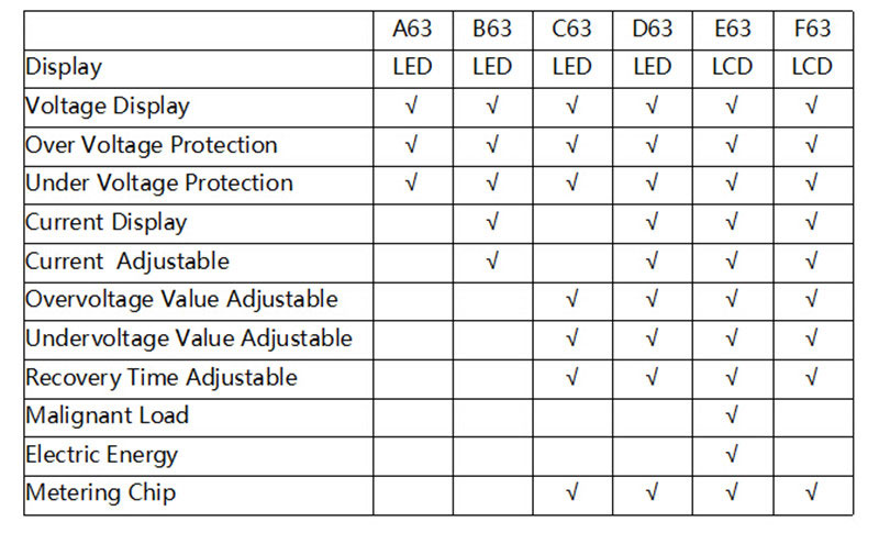
VIII.Different between others
I have a client in Iran. He want US-52 and SS-22 speed controller in October. I sent a PI to him after sending price and freight charge, but i forgot to add freight...
This month our company launched a voucher, in order to appreciate the support from clients. When the client's goods value reached the setted amount, the voucher will...
Winston Wish You Marry Christmas!
Time in a hurry, in the beginning of the new year, we will be better customer service, quality is our culture, to give customers what they want. Winston returen work...