


Inverter, maybe everyone knows that there is such a thing and what it is used for, but if you introduce it to others, most of you may not know how to say it. Because there are many things we know in life but don’t understand it. Of course, I believe that people who understand electricity or decoration industries still know about frequency converters. Next, the Chinese frequency inverter manufacturer mainly introduced to you what is an inverter.
Inverter introduction
The frequency converter is a power control device that uses frequency conversion technology and microelectronics technology to control the AC motor by changing the frequency of the motor's working power supply.
Chinese frequency inverter manufacturer tell you that the inverter is mainly composed of rectification (AC to DC), filtering, inverter (DC to AC), braking unit, drive unit, a detection unit, micro-processing unit, etc.
The frequency converter adjusts the voltage and frequency of the output power supply by switching off the internal IGBT, and provides the required power supply voltage according to the actual needs of the motor, thereby achieving the purpose of energy saving and speed regulation.
Advantages of using frequency converters
(1) Provide a soft start function to reduce the starting current of the motor so that it will not generate surges, thereby reducing the mechanical stress of the motor and improving its stability of the motor;
(2) It reduces the difficulty of building the power grid, and there is no need to consider the impact of the current on the power grid when the motor starts;
(3) The Chinese frequency converter manufacturer tells you that it reduces the harmonic interference to the power grid when the motor is running;
(4) Realize step-less speed regulation (in actual use, it can be equipped with a speed sensor, PLC, etc. to achieve automatic step-less speed regulation);
(5) Speed down as needed to reduce power consumption;
(6) It can improve the power factor of the whole power system;
(7) Monitor system performance in an orderly manner, and quantify the energy consumption ratio.
Inverter classification
According to the classification of the main circuit and working filtering method, it can be divided into voltage type inverter and current type inverter.
According to the switching mode, it can be divided into PAM control frequency converter, PWM control frequency converter, and high carrier frequency PWM control frequency converter.
According to the classification of the working principle, it can be divided into V/f control inverter, slip frequency control inverter, and vector control inverter.
Classified according to the purpose, it can be divided into general-purpose inverters, high-performance dedicated inverters, high-frequency inverters, single-phase inverters, and three-phase inverters.
Application field
(1) Petroleum: oil transfer pumps, electric submersible pumps, water injection pumps, pumping units, etc.;
(2) Construction: elevators, conveyor belts, air conditioning equipment, blowers, pumps, etc.;
(3) Paper industry: paper machines, pumps, pulverizers, fans, mixers, blowers, and other electronics;
(4) Manufacturing industry: air compressors, injection molding machines, central air conditioners, fans, pumps, conveyor belts, etc.
(5) Transportation: electric vehicles, electric locomotives, ship propulsion, air compressors, cable cars, etc.;
(6) Iron and steel: rolling mill, roller table, fan, pump, crane, ladle car, converter tilting, etc.;
(7) Steel wire: wire drawing machine, winding machine, blower, pump, hoisting machinery, cut-to-length, automatic feeding;
(8) Chemical industry: extruders, film conveyor belts, mixers, compressors, blowers, sprayers, pumps, etc.;
(9) Metallurgical industry: rolling mills, roller tables, blast furnace fans, pumps, hoisting machinery, blast furnace feeding, steel mill polishing, etc.
(10) Electric power: blower for boiler drum, feed water pump, centrifugal mixer, conveyor belt, pumping power station, flywheel, etc.;
(11) Mining industry: mud pumps, conveyor belts, hoists, cutting machines, digging machines, cranes, blowers, pumps, compressors, etc.;
(12) Cement: rotary kiln, hoisting machinery, blower, pump, main drive motor, conveyor belt, shaft kiln fan, etc.;
2. Commonly used control methods in inverters
1. Non-intelligent control mode
Non-intelligent control methods used in AC inverters include V/f control, slip frequency control, vector control, and direct torque control.
(1) V/f control
V/f is the ratio of the voltage applied to the motor stator to the frequency of the power supply.
★Control features: The output voltage of the frequency converter is changed in proportion to the output frequency through the voltage-frequency converter, that is, v/f=constant.
★Performance characteristics: high-cost performance, constant output torque, that is, constant magnetic flux control, but the precision of speed control is not high. It is suitable for occasions where the purpose of energy saving is low and the requirements for speed accuracy are low.
★Poor low-frequency stability: When running at low speed, it will cause insufficient torque, and torque compensation is required.
The inverter is open-loop control, and easy to install and debug.
(2) Slip frequency control
Slip frequency control is a control method that directly controls the torque. It is based on V/f control, according to knowing the power frequency corresponding to the actual speed of the asynchronous motor, and adjusting the frequency converter according to the desired torque. The output frequency can make the motor have a corresponding output torque.
This control method needs to install a speed sensor in the control system, and sometimes current feedback is added to control the frequency and current. Therefore, this is a closed-loop control method that can make the inverter have good stability and control Rapid acceleration and deceleration and load changes have good response characteristics.
(3) Vector control
Vector control is to control the magnitude and phase of the motor stator current through the vector coordinate circuit, so as to control the excitation current and torque current of the motor in the d, q, and 0 coordinate axes respectively, and then achieve the purpose of controlling the motor torque. By controlling the action sequence and time of each vector and the action time of the zero vector, various PWM waves can be formed to achieve various control purposes. For example, a PWM wave with the least switching times is formed to reduce switching loss. Currently, there are two vector control methods that are actually used in frequency converters: the vector control method based on slip frequency control and the vector control method without a speed sensor.
(4) Direct torque control
Direct torque control uses the concept of space vector coordinates to analyze the mathematical model of the AC motor in the stator coordinate system, controls the flux linkage and torque of the motor, and achieves the purpose of observing the stator flux linkage by detecting the stator resistance.
2. Intelligent control method
Intelligent control methods mainly include neural network control, fuzzy control, expert system, learning control, etc. There are some successful examples in specific applications of using intelligent control methods in the control of frequency converters.
Inverter Maintenance Faults and Troubleshooting Methods
1. The switching power supply of the inverter is damaged
This is a common failure of many inverters. It is usually caused by damage to the components of the switching power supply or short-circuit of the load. You should first consider whether the switching power supply is damaged (usually uc2844 or resistor is damaged). If you can't judge whether the power supply is faulty, you can test it with an external 24v power supply. If the test results are normal, it can be judged as a power supply fault.
2. The letter "14" alarm is displayed on the LCD screen of the frequency converter
"alarm 14" appears on the LCD screen of the inverter, and the inverter cannot work. Press the reset button after re-powering to reset, and it will alarm again when restarting. Check the operation manual for a grounding alarm. Check that the motor and related cables are not grounded. , that is to say, the fault is in the frequency converter. The reason for the grounding alarm caused by the analysis circuit is that the output voltage signal of the hall sensor is sent to the current sampling board and then sent to the operational amplifier for comparison. The resistance value of one path has become infinite due to corrosion, so the grounding is poor, causing the signal to be too strong, causing an alarm, and there is no original replacement. Weld the same resistance value high-power chip resistor on it, and it runs normally after restarting. Grounding faults are common faults. In addition to eliminating the cause of motor grounding problems, the most likely faults are Hall sensors and signal transmission resistors, because they are more affected by environmental factors such as temperature, humidity, and corrosive gases. Large, the working point is prone to drift, resulting in a grounding alarm.
3. Overcurrent alarm
When restarting, it trips as soon as the speed increases. This is a very serious phenomenon of overcurrent. The main reasons are contactor open circuit, heavy load, mechanical part failure; inverter module damage; motor torque being too small, etc.
The alarm is immediately powered on, this phenomenon generally cannot be reset. The main reasons are module damage, drive circuit damage and current detection circuit damage.
4. Heat sink temperature is the too high alarm
First, check whether the temperature displayed on the panel exceeds the upper limit of the parameter setting. If it exceeds, check whether it matches the actual temperature. If it does not match, it means that the detection circuit is faulty. After checking, the temperature does not match the reality. The 14v of the test circuit is normal, and there is no voltage at both end of the plug. , Check the resistance value of resistors R207 and R208 to be infinite, and everything is normal after replacing the new one.
5. The inverter can start with frequency and without voltage
The inverter display is normal, and it can start there is a frequency change but no AC voltage is generated. The fault of the control board is still the same, indicating that the fault is in the power part. The IGBT and related circuits are normal. When the wiring of mk1-mk2 is found, it is found The contact resistance of the wiring on the cable is too large due to corrosion. After repairing it with alcohol and a sharp needle, it is correct and then powered on again. Everything is normal.
6. The display of the inverter panel is good and bad
The Chinese frequency inverter manufacturer tells you that the display on the inverter panel is sometimes good and sometimes bad, and the fault remains the same when the control board is replaced. It is suspected that the power supply is in poor contact. Check the power supplies and everything is normal. Measure the line row between the power board and the control board and find that there is a wired contact. Bad, after renewing the power, everything is normal.
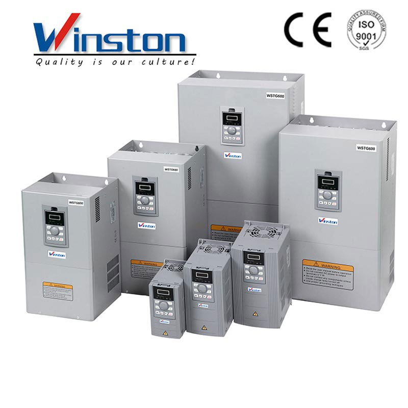
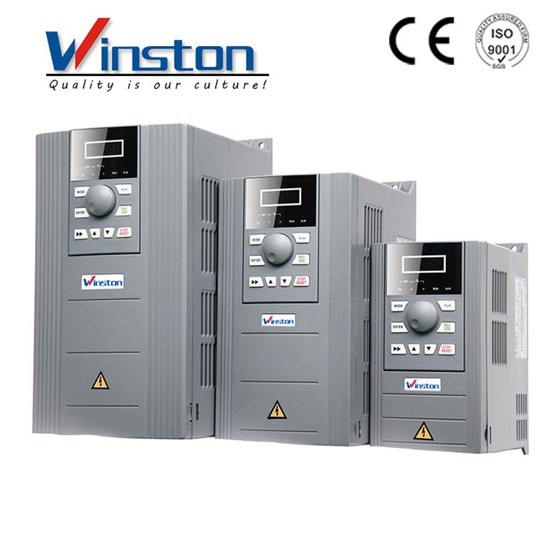
Which company produces inverters?
Yueqing Winston Electric Co., Ltd. As a professional frequency inverter manufacturer and supplier in China, all inverters have passed the international industry certification standards, you can be completely assured of the quality. If you do not find your own inverter in our product list, you can also contact us and we will solve the problem together with you.
GET A QUOTE