
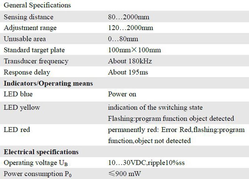
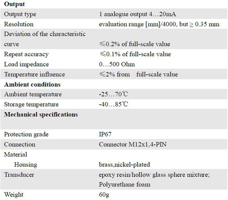
Technical data
The sensor can be synchronised by the external application of a square wave voltage. A synchronisation pulse at the synchronisation input starts a measuring cycle. The pulse must have a duration greater than 100 μs. The measuring cycle starts with the falling edge of a synchronisation pulse. A low level > 1 s or an open synchronisation input will result in the normal operation of the sensor. A high level at the synchronisation input disables the sensor.
Two operating modes are available:
1. Multiple sensors can be controlled by the same synchronisation signal. The sensors are synchronised.
2. The synchronisation pulses are sent cyclically to individual sensors. The sensors operate in multiplex mode.
Internal synchronization
The synchronisation connections of up to 5 sensors capable of internal synchronisation are connected to one another. When power is applied, these sensors will operate in multiplex mode.
The response delay increases according to the number of sensors to be synchronised. Synchronisation cannot be performed during TEACH-IN and vice versa. The sensors must be operated in an unsynchronised manner to teach the evaluation limits.
Note:
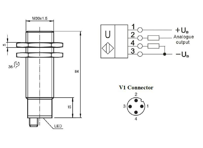
If the option for synchronisation is not used, the synchronisation input has to be connected to ground (0V) or the sensor has to be operated via a V1 cable connector (4-pin).
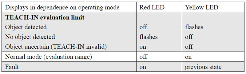
The ultrasonic sensor features an analogue output with two teachable evaluation limits. These are set by applying the supply voltage - UB or + UB to the TEACH-IN input. The supply voltage must be applied to the TEACH-IN input for at least 1 s. LEDs indicate whether the sensor has recognised the target during the TEACH-IN procedure. The lower evaluation limit A1 is taught with - UB, A2 with + UB.
Two different output functions can be set:
1. Analogue value increases with rising distance to object (rising ramp)
2. Analogue value falls with rising distance to object (falling ramp) Evaluation limits may only be specified within the first 5 minutes after Power on. To modify the evaluation limits later, the user may specify the desired values only after a new Power On.
TEACH-IN rising ramp (A2 > A1)
- Position object at lower evaluation limit
- TEACH-IN lower limit A1 with - UB
- Position object at upper evaluation limit
- TEACH-IN upper limit A2 with + UB
TEACH-IN falling ramp (A1 > A2):
- Position object at lower evaluation limit
- TEACH-IN lower limit A2 with + UB
- Position object at upper evaluation limit
- TEACH-IN upper limit A1 with - UB
Default setting
A1: unusable area
A2: nominal sensing range
Mode of operation: rising ramp
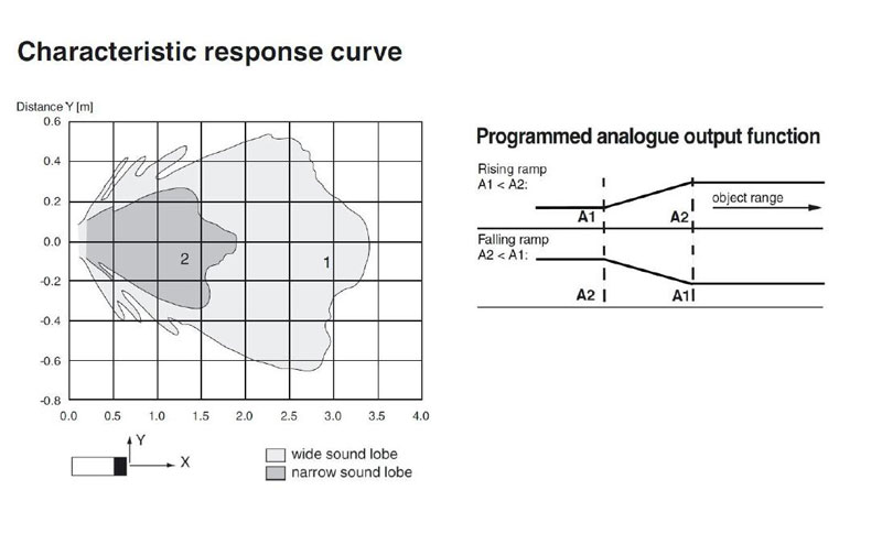
The ultrasonic sensor enables two different shapes of the sound cone, a wide angle sound cone and a small angle sound cone.
1. Small angle sound cone
- switch off the power supply
- connect the Teach-input wire to -UB
- switch on the power supply
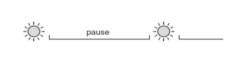
- the red LED flashes once with a pause before the next.
- yellow LED: permanently on: indicates the presence of an object or disturbing object within the sensing range
- disconnect the Teach-input wire from -UB and the changing is saved
2. Wide angle sound cone
- switch off the power supply
- connect the Teach-input wire with + UB
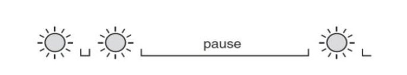
- switch on the power supply
- the red LED double-flashes with a long pause before the next.
- yellow LED: permanently on: indicates an object or disturbing object within the sensing range
- disconnect the Teach-input wire from + UB and the changing is saved
Installation conditions
If the sensor is installed at the environment temperature fall below 0℃,It should do well on the protective measures. In case of direct mounting of the sensor in a through hole using the steel nuts, it has to be fixed at the middle of the housing thread.
GET A QUOTE
.jpg)